In modern Azure environments, it is common to deploy resources across multiple virtual networks (VNets). These networks may be separated for reasons such as security boundaries, environment isolation (production, staging, development), regional placement, or organizational structure. However, while isolation is important, resources in different VNets often still need to communicate with each other.
Azure Virtual Network Peering allows resources in two VNets to communicate through private IP addresses over the Microsoft backbone network. Peering adds system routes between the connected address spaces, but the VNets remain separate administrative and policy scopes. NSGs, user-defined routes, firewalls, DNS configuration, and resource permissions still apply.
If these concepts are new, read Azure Networking first. This introductory portal lab is complemented by the deeper hub-and-spoke and non-transitive peering guide.
What is Azure Virtual Network?
Azure Virtual Network is the fundamental building block for your private network in Azure. A virtual network enables many types of Azure resources, such as Azure Virtual Machines (VM), to securely communicate with each other, the internet, and on-premises networks. A virtual network is similar to a traditional network that you'd operate in your own data center. An Azure Virtual Network brings with it extra benefits of Azure's infrastructure such as scale, availability, and isolation.
What Is Virtual Network Peering?
Virtual network peering links virtual networks, enabling resources to route traffic between the peered address spaces using private IP addresses. The VNets must have non-overlapping address spaces. Peering isn't transitive: if VNet A is peered with B and B is peered with C, A doesn't automatically receive connectivity to C.
Supported Peering Types
Virtual network peering: Connecting virtual networks within the same Azure region.
Global virtual network peering: Connecting virtual networks across Azure regions.
Build in the cloud with an Azure free account
Are you ready to follow along with this tutorial? If your answer is Yes! Then click here to register for Azure Subscription.
Limits and Pricing
Creating a VNet doesn't itself add an hourly VNet charge, but data transfer, public IPs, gateways, Bastion, firewalls, and other resources can be billed. Peering data-transfer pricing depends on the regions and traffic direction. Limits also change over time, so don't hardcode the old “50 VNets” figure; use Microsoft's current networking limits and the Azure pricing calculator during design.
Click the link to read more: Virtual Network Pricing | Microsoft Azure
Overview
We will be creating two virtual networks and we will be naming them abcofcloudVNetHQ and abcofcloudVNetBranch, after creating the virtual networks, we will then create two virtual machines named VM1 and VM2. VM1 will be placed in a subnet in abcofcloudVNetHQ and VM2 will be placed in a subnet in abcofcloudVNetBranch.
Creating a Virtual Network
We will start with creating the abcofcloudVNetHQ.
Step 1: Sign into the Azure Portal.
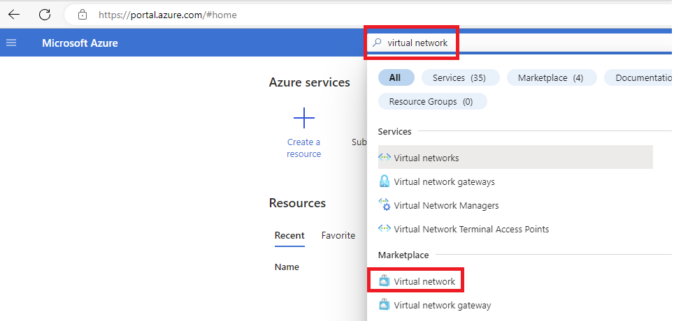
Step 2: Search for virtual network in the Azure portal search box.
Step 3: In the search results, select virtual network right under Marketplace.
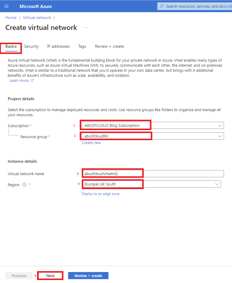
Step 5: Under the Basics tab, choose the Subscription you want to use for this virtual network.
Step 6: A Resource group can be selected from the existing resource group, or a new resource group can be created by clicking on Create new. We will be using the abcofcloudRG for this tutorial.
Step 7: Enter a preferred name for the virtual network, for this tutorial, we will be naming the virtual network abcofcloudVNetHQ.
Step 8: Choose a preferred location for the virtual network, by clicking on the drop-down and selecting the region you prefer, and then clicking on Next at the bottom, we will be using the UK South for this tutorial.
For this tutorial, we will leave the Security tab with the default settings and click on Next.
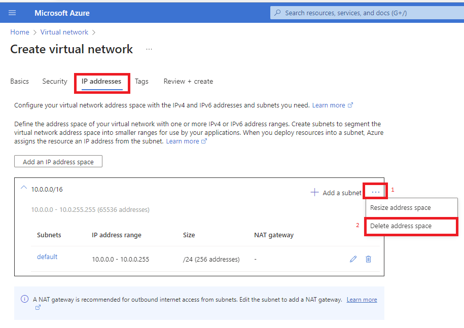
We will be using the 172.20.0.0/16 for our address space and for the subnet, we will be using 172.20.0.0/24 for the Subnet Address range.
Step 9: Click on the 3 dots beside the Add a subnet and then click on the Delete address space.
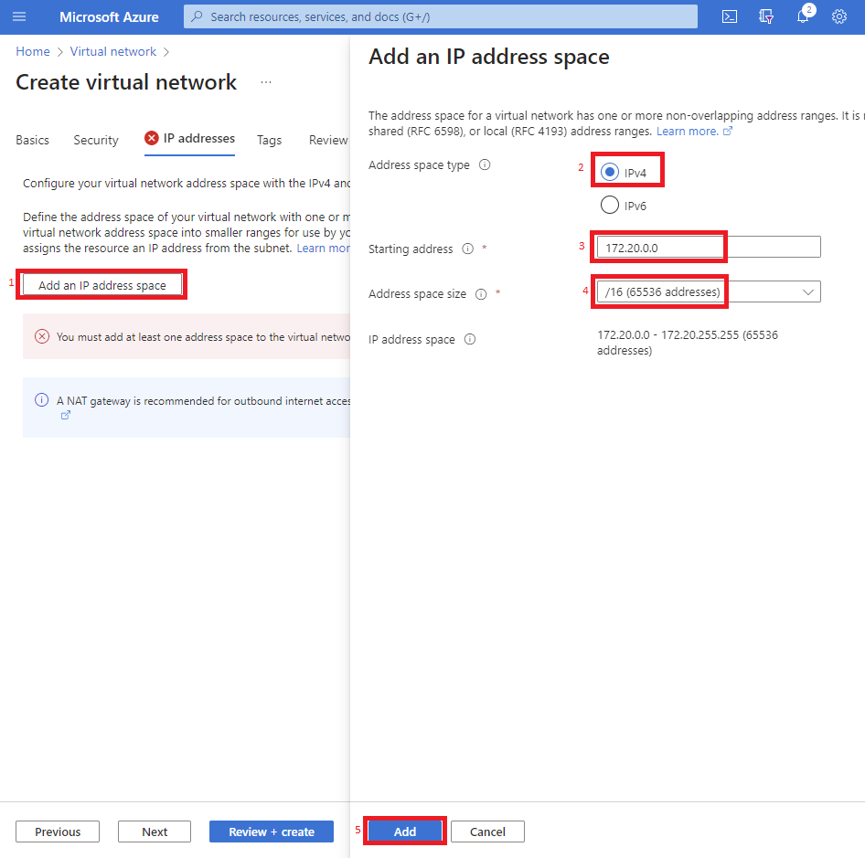
Step 10: click on the Add an IP address space, and select the IPv4 with the Starting address as 172.20.0.0, the Address space size will be /16 (65536 addresses) then click on Add.
Step 11: Select the + Add a subnet button and enter the HQSubnet1 for the Subnet Name and the Starting address as 172.20.0.0 with the Subnet size as /24 (256 addresses) and then click on Add.
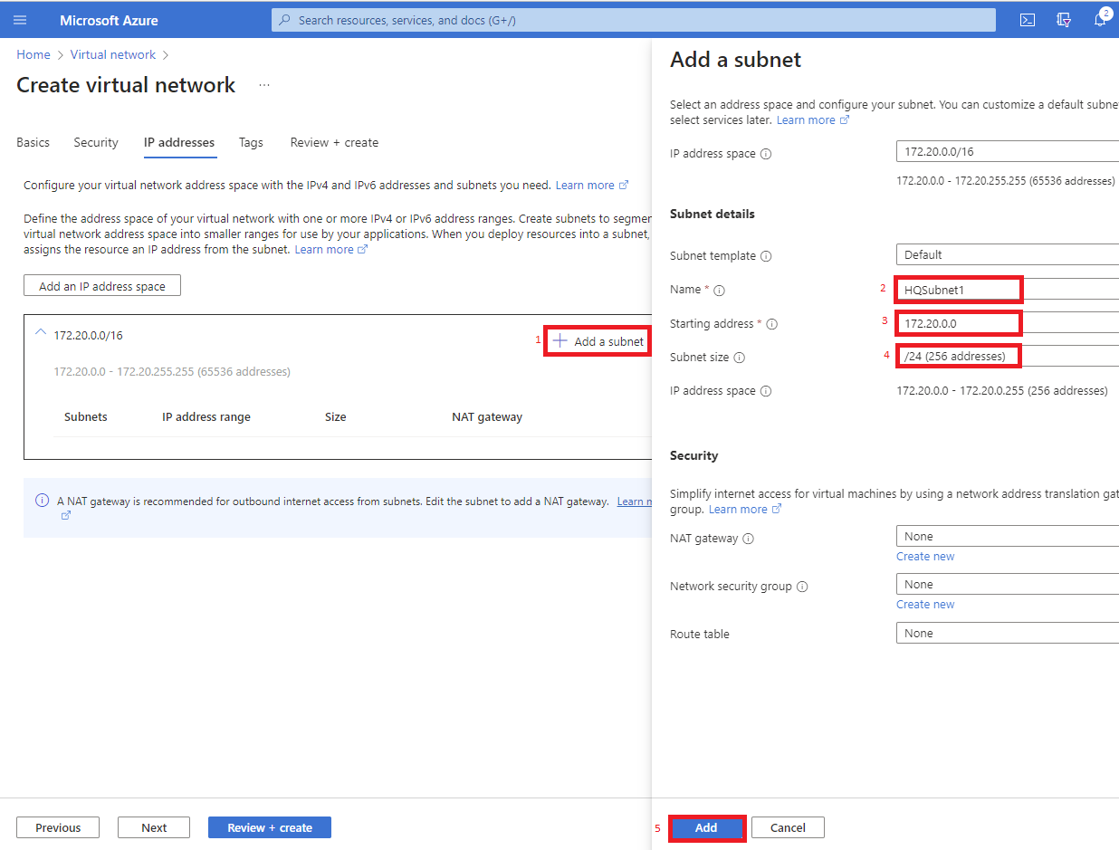
Once that is done click on Review + Create and select Create.
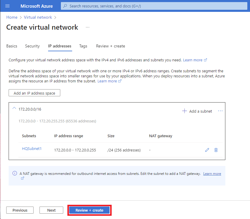
What we need to do next is create the second Virtual Network which is abcofcloudVNetBranch using the same procedure from Step 1 to Step 11 but we just need to make a few changes.
Resource group: abcofcloudRG
Virtual network name: abcofcloudVNetBranch
Region: UK South
IP Address space: 172.22.0.0/16
Subnet name: BranchSubnet1
Starting Address: 172.22.0.0
Subnet size: /24 (256 addresses).
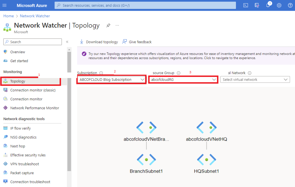
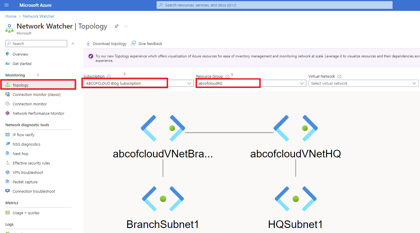
Bonus: After creating both virtual networks, in the search box at the top type Network Watcher and on the Network Watcher page click on Topology. Select the Subscription and the Resource Group, you will see both virtual networks and their subnets, but once the peering is added you will see a line showing the peering has been added.
Create the Virtual Network Peering
This is the point where we will peer the virtual networks, for us to do that we need to locate the virtual network we created. We can either do this by going to the Resource group “abcofcloudRG” or using the search box.
Step 1: Search for abcofcloudVNetHQ in the Azure portal search box and select it.
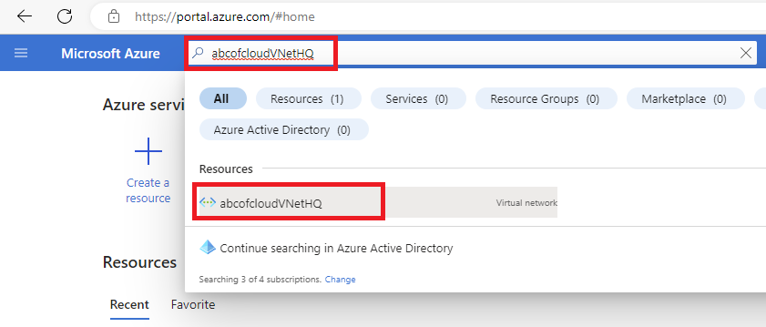
Step 2: On the abcofcloudVNetHQ virtual network page, click on Peerings Under the Settings area and then click on + Add.
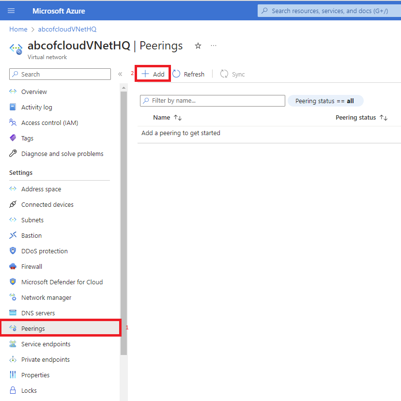
Once that is done, we need to add peering from this virtual network “abcofcloudVNetHQ” to the remote virtual network “abcofcloudVNetBranch”.
Step 3: Now that we are on the Add peering page, we need to choose a preferred name for the peering link name for this virtual network, and for this tutorial, I will be using the abcofcloudVNetHQ-to-abcofcloudVNetBranch.
Step 4: Since the goal is direct communication between resources in both VNets, leave Traffic to remote virtual network allowed. I keep forwarded traffic disabled unless a deliberate network virtual appliance or routing design requires it. Leave gateway or Route Server options disabled for this direct-peering lab.
These settings are independent in each peering direction:
- Allow virtual network access enables direct traffic from the remote VNet.
- Allow forwarded traffic permits traffic whose original source isn't inside the remote VNet, such as traffic forwarded by an NVA.
- Allow gateway transit lets the local gateway advertise transit to a peered VNet.
- Use remote gateways lets this VNet use the peer's gateway and has topology constraints.
Don't enable transit flags merely to clear a connectivity error; first confirm the intended routing architecture.
Step 5: Now it is time to give a preferred name to the Remote virtual network peering link name, you will see the name I will be using is the reverse name of the virtual network peering link name, because we are going to be deciding how the remote virtual network should handle the communication. The preferred name I will be using for this tutorial is abcofcloudVNetBranch-to-abcofcloudVNetHQ.
The Virtual network deployment model will be Resource manager, we won’t be using the resource ID for this tutorial instead, we will select the subscription of the virtual network we wish to peer.
Step 6: We will then select the Virtual network from the drop-down which is abcofcloudVNetBranch.
Every other thing will be left as default same way we did earlier and then we click on Add.
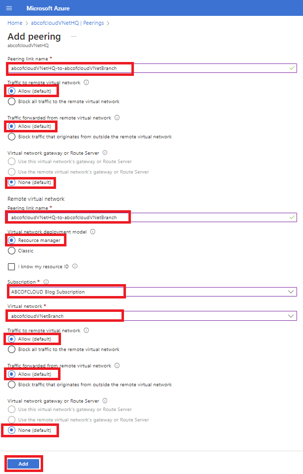
Note: The remote virtual network can be in the same region of abcofcloudVNetHQ or in a different region.
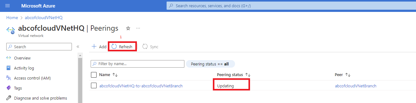
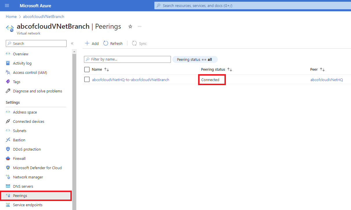
Once the Add button is selected the peering status will be showing updating and this will take a few minutes, if it doesn’t change, click on the Refresh button at the top, beside the + Add button and it will change to Connected.
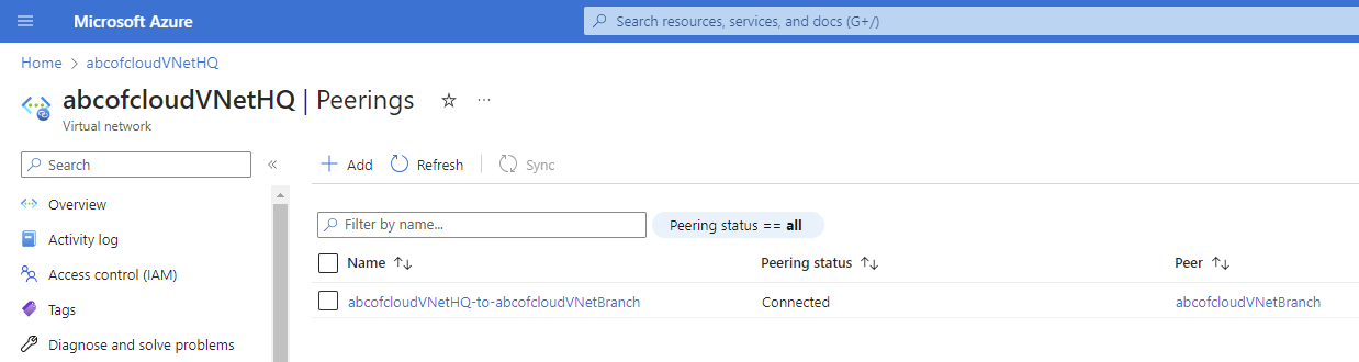
Note: You can search for the virtual network abcofcloudVNetBranch and on the virtual network page click on Peerings, you will also find the peering that was added with Peering status Connected.
Bonus: Let's use the Network Watcher and see what has been added, you will notice there is now a line showing a peering between both virtual networks.
To verify the data path, create one test VM in each VNet and test a specific private-IP connection. The VM section focuses only on network placement; read Azure Compute for VM sizing, identity, availability, patching, and disk decisions.
Create Private Test Virtual Machines
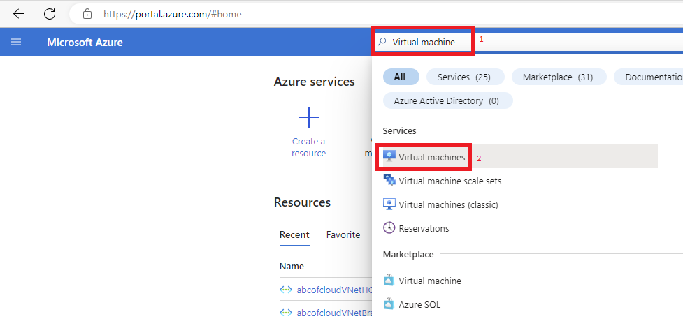
Step 1: In the search box in the Azure portal type Virtual Machine and then click on Virtual Machine under Marketplace.
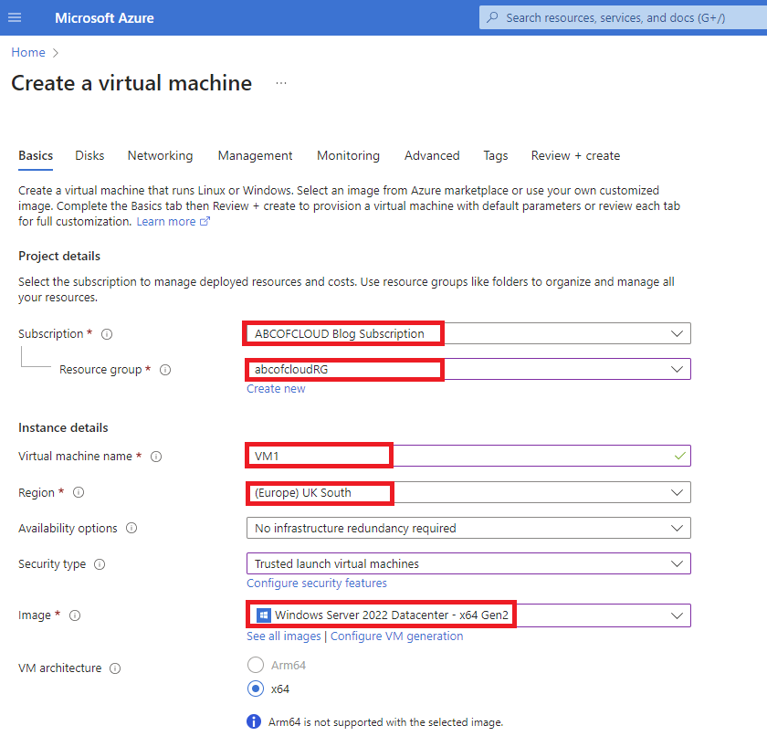
Step 2: We will choose our preferred Subscription,
Resource group: abcofcloudRG
Virtual machine name: VM1
Region: UK South
Image: Windows Server 2022 Datacenter – x64 Gen2
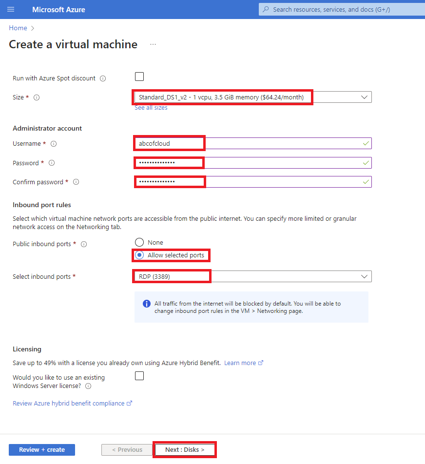
Size: Standard_DS1_v2
Username: abcofcloud
Password: Enter a password of your choosing. The password must be at least 12 characters long and meet the defined complexity requirements.
Public inbound ports: None for the recommended design.
I use Azure Bastion, the Point-to-Site VPN guide, or another controlled private management path. The original screenshots show the portal's public-IP/RDP choices, but a professional deployment shouldn't expose TCP 3389 to the internet.
Step 3: Click on Next: Disks and leave everything on the Disk tab as default, and then Click on Next: Networking.
Step 4: On the Networking tab;
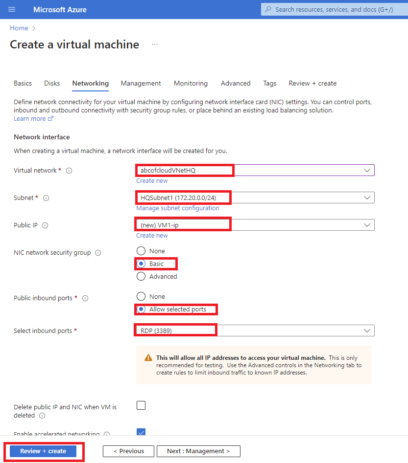
Virtual network: abcofcloudVNetHQ
Subnet: HQSubnet1 (172.20.0.0/24)
Public IP: None
NIC network security group: Basic
Public inbound ports: None
Click on Review + Create to validate and then click on Create.
Step 5: We will be creating the second Virtual Machine called VM2 but the VM will be placed in the abcofcloudVNetBranch virtual network. Repeat the steps from Step 1 to Step 4
Virtual machine name: VM2
Virtual network: abcofcloudVNetBranch
Subnet: BranchSubnet1 (172.22.0.0/24).
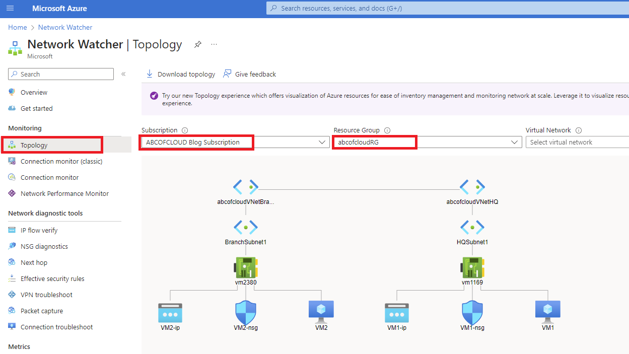
Bonus: Let’s take a look at Network Watcher and see what it looks like, you will see the VM1 and VM2 in the different virtual networks.
Verify Private Connectivity
The preferred verification is a connection to a known application port on VM2's private IP. I use Bastion or P2S to access VM1, then test VM2. This validates the peering route together with the NSG and guest firewall rules that the workload actually needs.
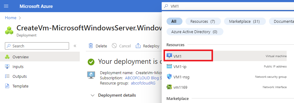
Step 1: Search for VM1 using the search box in the Azure portal and then click on VM1.
Step 2: On the VM1 page, select Connect and use Azure Bastion or your configured private management path.
Step 3: Connect to VM1's private IP. If you deliberately reproduce the original public-RDP lab shown in the screenshots, restrict the NSG source to your current public /32, use it only temporarily, and remove the public IP and rule immediately afterward.
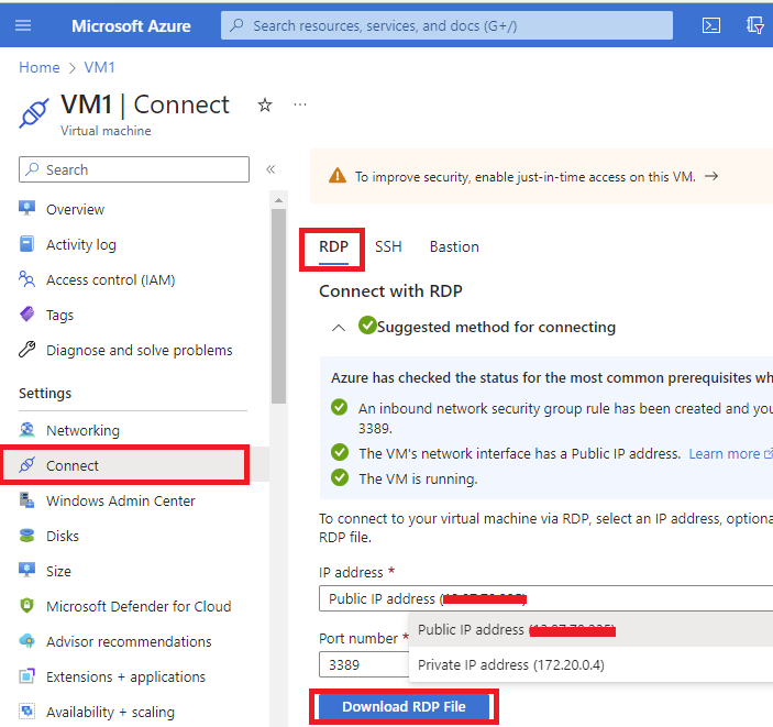
Step 4: Open the downloaded RDP file and click on connect if prompted.
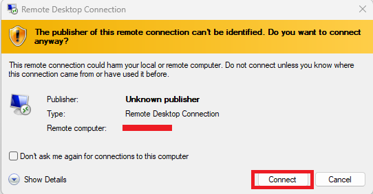
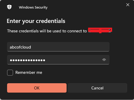
Step 5: Enter the username and password you specified when creating yours and when we get a warning about the certificate, we will select Yes and continue with the connection.
We will repeat from Step 1 to Step 5 for VM2 so we can connect to VM2.
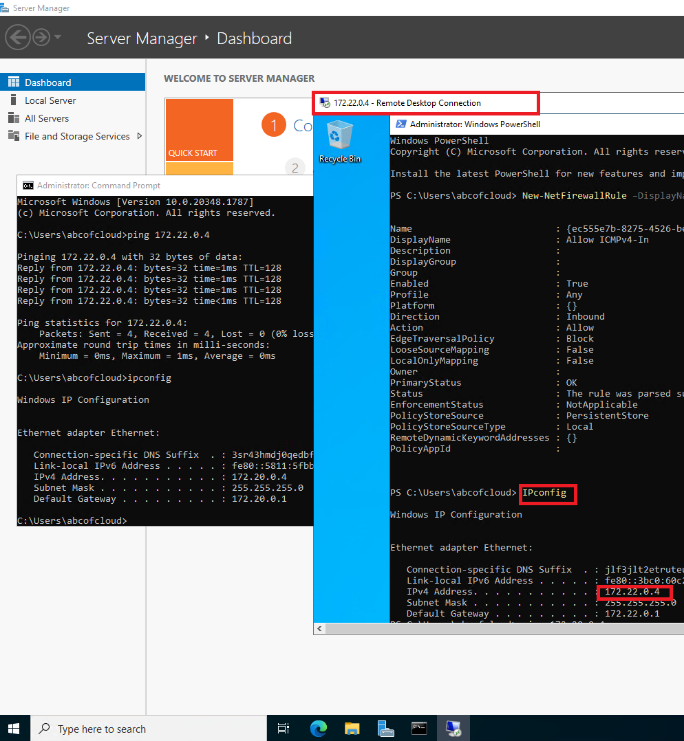
Note: We will test communication using ping from VM1 to VM2. Ping uses the Internet Control Message Protocol (ICMP). By default, the Windows Firewall blocks ICMP Echo Requests (Pings) from the network. And they’re different ways to allow it but for this tutorial, We will be using the PowerShell cmdlet to enable ICMP on VM2.
ICMP can be useful operationally when it is deliberately scoped. It is neither proof that every application path works nor inherently forbidden in production. Prefer testing the exact TCP or UDP port used by the workload.
Step 6: For this lab, create a scoped ICMP rule on VM2. Replace the source with VM1's private IP or the smallest appropriate subnet range:
New-NetFirewallRule `
    -DisplayName 'Allow ICMPv4 from HQ test VM' `
    -Direction Inbound `
    -Protocol ICMPv4 `
    -IcmpType 8 `
    -RemoteAddress '172.20.0.4' `
    -Action Allow
For an application-aware test, run Test-NetConnection 172.22.0.4 -Port <application-port> after configuring the corresponding NSG and guest-firewall rule.
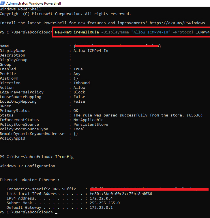
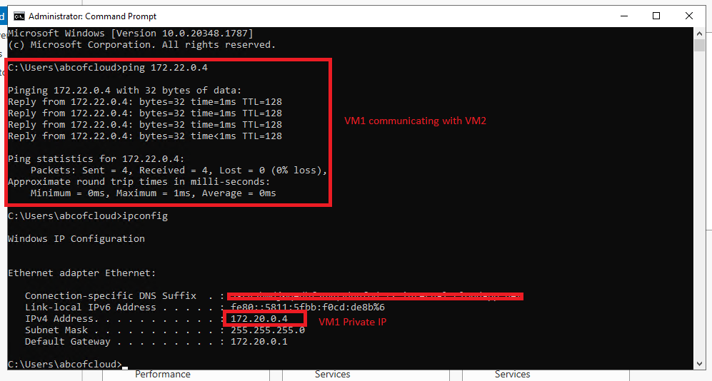
Step 7: From VM1 open the command prompt and type “ping 172.22.0.4” without the quote, this (172.22.0.4) is the private IP address for VM2.
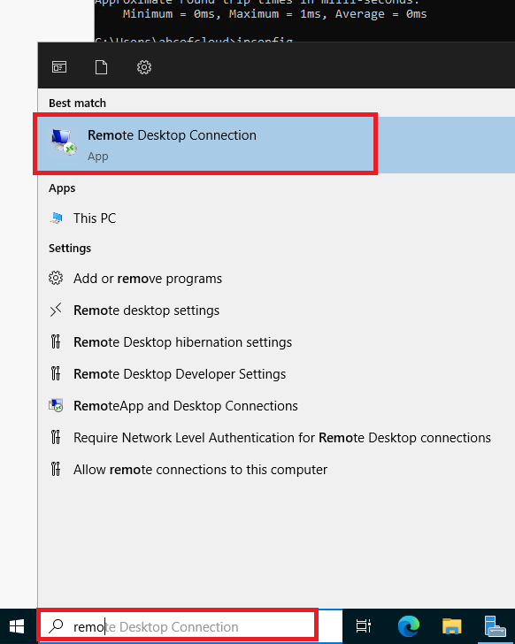
Step 8: In VM1 beside the Start Menu, we will search for Remote Desktop Connection and click on it.
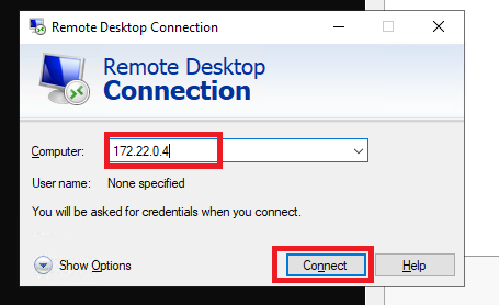
Step 9: We are going to type in the Private IP of VM2 (172.22.0.4) and click on Connect.
Step 10: We will input the username and password and then click on Ok. When we get a warning about the certificate, we will select Yes and continue with the connection.
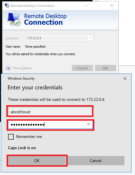
We can now confirm that both resources in different virtual networks can communicate.
Troubleshooting and Operational Checks
If the connection fails, check the layers in order:
- Both peering links show Connected rather than Initiated or Disconnected.
- The VNet address spaces don't overlap and the destination private IP is correct.
- Effective routes on the source NIC contain a route for the remote VNet with next hop
VNetPeering. - Effective NSG rules allow the test flow in both directions.
- The guest firewall and application are listening on the destination port.
- User-defined routes or an NVA aren't overriding the peering system route.
- Custom DNS or Private DNS zone links provide the expected name resolution; peering alone doesn't merge private DNS namespaces.
Peering provides connectivity, not centralized inspection or transitive routing. Hub-and-spoke designs that use Azure Firewall or another NVA require forwarded-traffic settings and deliberate route tables.
Cleanup
Delete the two test VMs, disks, NICs, public IPs, Bastion resources, and peering lab resources when finished. If the resource group contains only the lab, deleting it is the simplest cleanup; otherwise delete only resources you have positively identified as lab-owned.