Spoke A was peered with the hub. Spoke B was peered with the same hub. Both peering relationships showed Connected.
Then a connection test from a workload in Spoke A to a workload in Spoke B timed out.
Nothing was wrong with the peering status. The mistake was assuming that the hub automatically became a transit router.
It did not.
Microsoft's Azure Virtual Network FAQ is explicit: transitive peering is not supported. If VNet A peers with VNet B, and VNet B peers with VNet C, Azure does not automatically peer A with C.
That rule applies directly to a customer-managed hub-and-spoke topology:
Spoke A --- Hub VNet --- Spoke B

Spoke A can reach the hub.
Spoke B can reach the hub.
Spoke A does not inherit a route to Spoke B.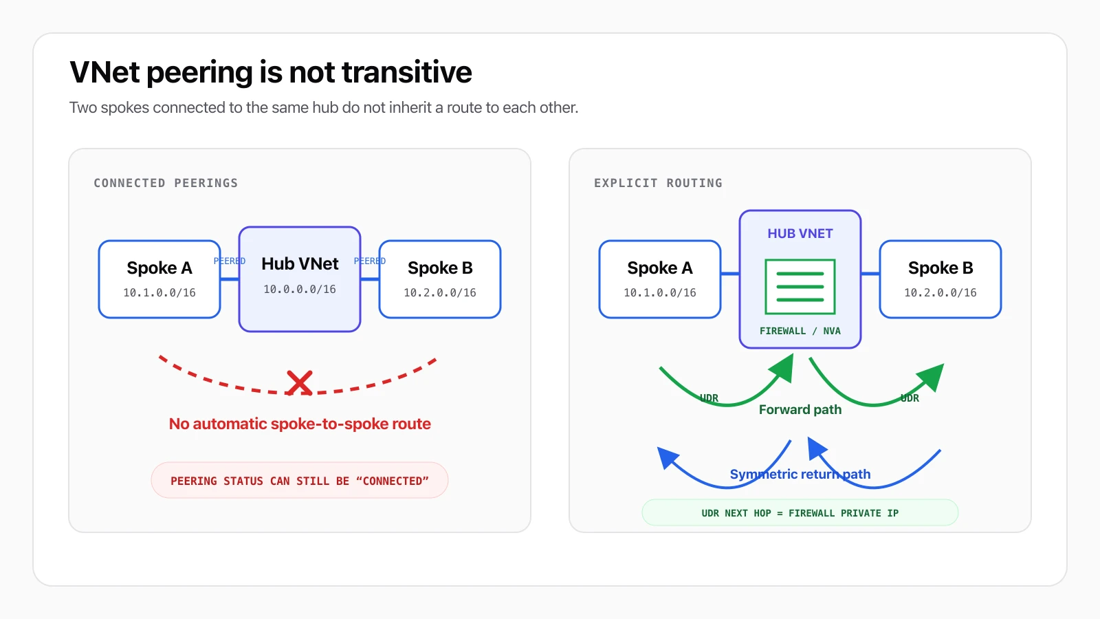
Connected hub-to-spoke peerings do not create a transitive route. A working routed design sends both directions through Azure Firewall or an NVA.
If you need the basic two-VNet setup first, follow How to Configure Virtual Network Peering in Azure. For the underlying VNet, subnet, NSG, and routing concepts, use the Azure Networking reference.
What Connected Actually Proves
A VNet peering is a relationship between exactly two virtual networks.
When the hub-to-Spoke-A peering is connected, Azure adds system routes for the hub's address ranges to Spoke A. When the hub-to-Spoke-B peering is connected, Azure does the same for Spoke B.
Those two facts do not create a third relationship between Spoke A and Spoke B.
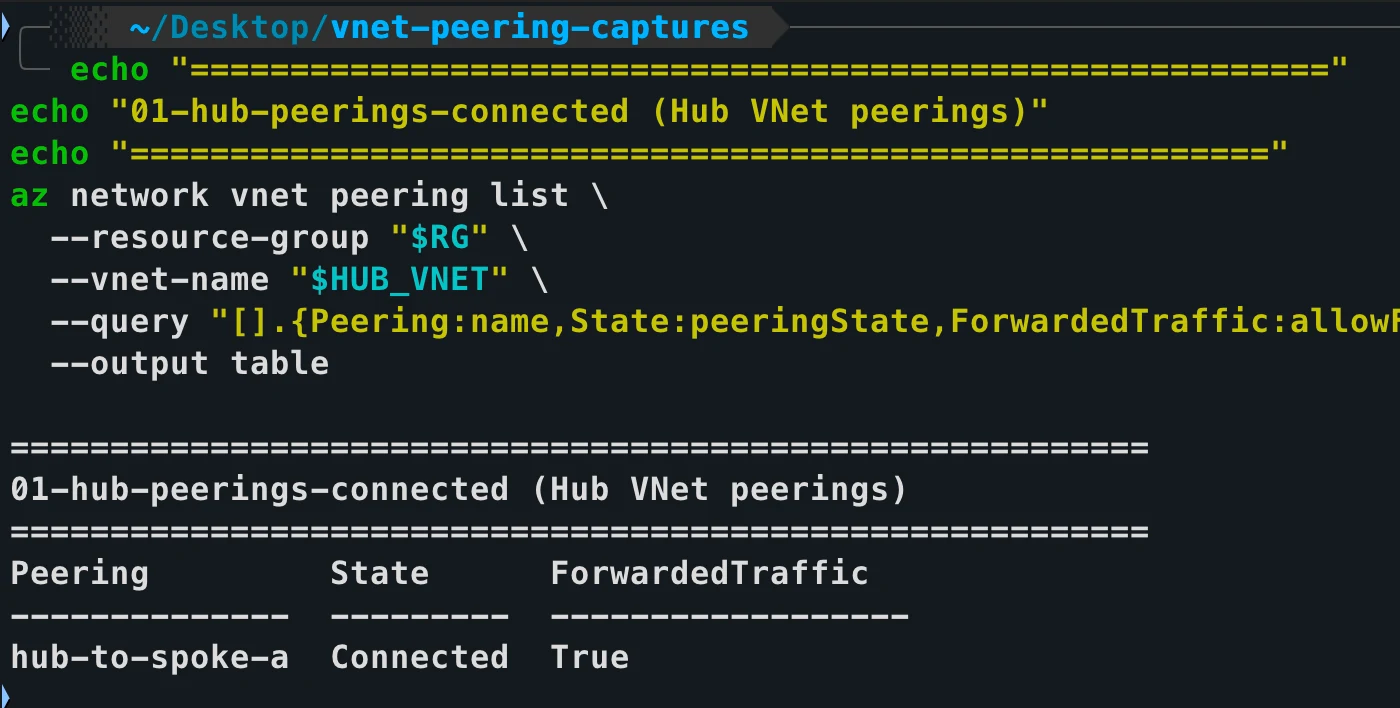
The hub-to-Spoke-A link is healthy and allows forwarded traffic. Connected still describes only this pairwise peering relationship.
Imagine this address plan:
| Network | Address space | Relationship |
|---|---|---|
| Hub VNet | 10.0.0.0/16 | Peered with both spokes |
| Spoke A | 10.1.0.0/16 | Peered only with the hub |
| Spoke B | 10.2.0.0/16 | Peered only with the hub |
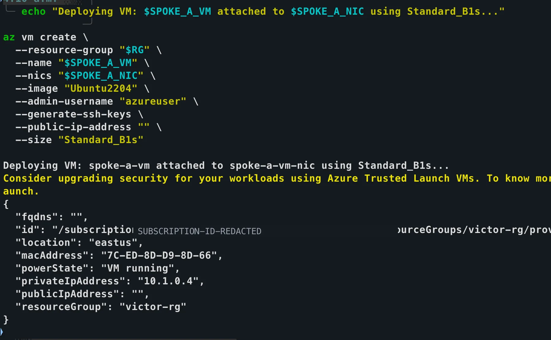
The test workload is attached to the Spoke A NIC and has no public IP. The subscription ID in the returned resource ID is covered before publication.
Without an additional route, a VM in Spoke A does not see 10.2.0.0/16 as a destination reachable through its hub peering. The ordinary hub VNet also does not inspect a packet and decide to forward it to its other peering connection.
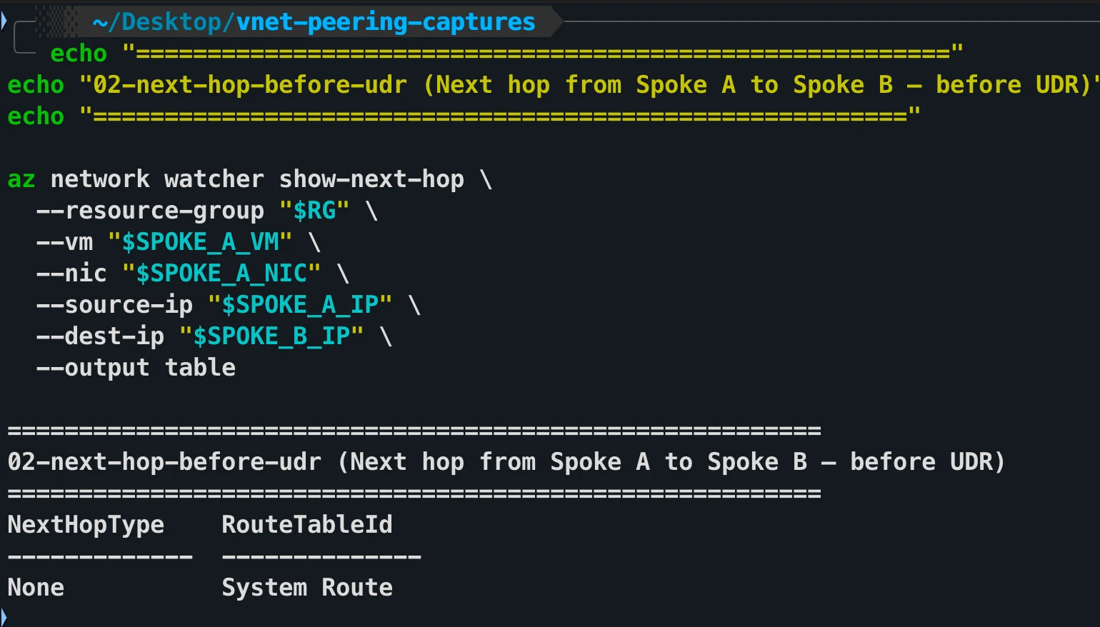
Before the UDR, Network Watcher reports NextHopType: None for the Spoke-A-to-Spoke-B destination even though the hub peering itself is Connected.
Connected does not mean transitive
A Connected status proves that the two ends of one peering relationship are established. It does not prove end-to-end reachability to a third VNet, and it does not validate NSGs, user-defined routes, firewall policy, or the guest operating system's firewall.
This is why the failure can feel silent. Azure does not report a broken peering because the peerings are not broken. The route that the architecture diagram implied simply does not exist.
Why the Hub Does Not Route Automatically
An ordinary Azure VNet is a network boundary, not a general-purpose transit router.
VNet peering gives the two peered networks direct private connectivity over Microsoft's backbone. It does not tell either network to forward traffic on behalf of another peering relationship.
The Microsoft hub-and-spoke design guide describes the same behavior: spokes can reach the hub, but cannot reach one another through it unless you configure routing or direct peering.
That leaves three common designs:
| Design | Spoke-to-spoke path | Use it when |
|---|---|---|
| Hub firewall or NVA | Spoke A → hub appliance → Spoke B | Central inspection and policy are required |
| Direct spoke peering | Spoke A → Spoke B | Low latency matters and bypassing central inspection is acceptable |
| Managed connectivity | Standard Azure Virtual WAN for transit, or Virtual Network Manager connected groups for direct connectivity | Azure should manage the chosen pattern at scale |
This article focuses on the first pattern: explicit routing through Azure Firewall or an NVA in a customer-managed hub.
The Working Traffic Path
For traffic to cross from one spoke to another through the hub, a routing component must actively forward it:
Spoke A subnet
    |
    | UDR: 10.2.0.0/16 -> 10.0.0.4
    v
Hub Azure Firewall or NVA
    |
    | firewall policy permits the flow
    v
Spoke B subnet

Return traffic:
Spoke B UDR: 10.1.0.0/16 -> 10.0.0.4
Four pieces have to agree:
- The hub must be peered with each spoke.
- The relevant peerings must allow forwarded traffic.
- Each spoke subnet must have a route that sends the other spoke's prefix to the firewall or NVA private IP.
- The firewall or NVA must permit and forward the traffic.
The route must be symmetric. If Spoke A sends traffic through the firewall but Spoke B returns it by a different path, a stateful firewall can drop the flow and troubleshooting becomes much harder.
Configure the UDRs with Azure CLI
The following example uses:
- Hub:
10.0.0.0/16 - Firewall or NVA private IP:
10.0.0.4 - Spoke A:
10.1.0.0/16 - Spoke B:
10.2.0.0/16
I create one route table for each spoke:
az network route-table create \
  --resource-group my-rg \
  --name spoke-a-rt

az network route-table create \
  --resource-group my-rg \
  --name spoke-b-rt
I add the route from Spoke A to Spoke B:
az network route-table route create \
  --resource-group my-rg \
  --route-table-name spoke-a-rt \
  --name to-spoke-b \
  --address-prefix 10.2.0.0/16 \
  --next-hop-type VirtualAppliance \
  --next-hop-ip-address 10.0.0.4
I add the matching return route from Spoke B to Spoke A:
az network route-table route create \
  --resource-group my-rg \
  --route-table-name spoke-b-rt \
  --name to-spoke-a \
  --address-prefix 10.1.0.0/16 \
  --next-hop-type VirtualAppliance \
  --next-hop-ip-address 10.0.0.4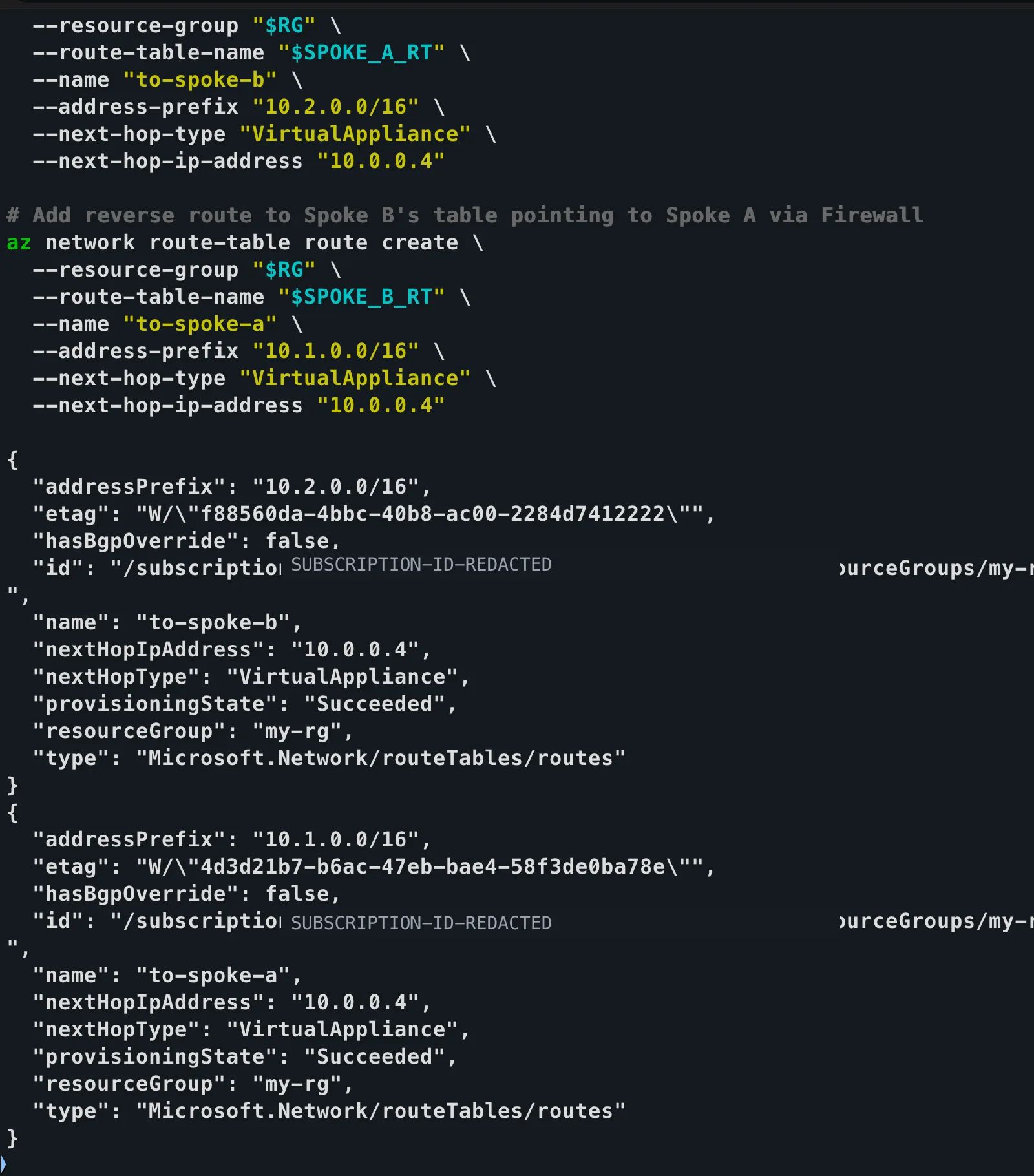
Both route creations succeeded: Spoke A sends 10.2.0.0/16 to the hub appliance, and Spoke B sends 10.1.0.0/16 back through the same next hop.
Associate each route table with the workload subnet that should use it:
az network vnet subnet update \
  --resource-group my-rg \
  --vnet-name spoke-a-vnet \
  --name workload-subnet \
  --route-table spoke-a-rt

az network vnet subnet update \
  --resource-group my-rg \
  --vnet-name spoke-b-vnet \
  --name workload-subnet \
  --route-table spoke-b-rt
The Microsoft route-table tutorial uses the same VirtualAppliance next-hop type and private next-hop IP pattern.
These example routes are deliberately scoped to the opposite spoke prefixes. Microsoft's current hub-and-spoke design guide also documents a standard pattern that uses 0.0.0.0/0 to send all outbound traffic, including spoke-to-spoke traffic, through the hub firewall. Choose the route scope that matches your intended inspection and egress design; do not add a default route casually.
A UDR is attached to a subnet
Creating a route table is not enough. Azure combines its routes with a subnet's system routes only after you associate the route table with that subnet.
Allow Forwarded Traffic on the Peerings
The packet arriving at a spoke from the hub firewall did not originate in the hub. It is forwarded traffic from the other spoke.
For the appliance-routed design, configure the hub/spoke peering relationships to allow forwarded traffic. Microsoft's hub-spoke reference architecture and VNet peering tutorial both call out this setting.
I check both directions of both peering relationships:
- Hub → Spoke A and Spoke A → Hub
- Hub → Spoke B and Spoke B → Hub
I do not confuse Allow forwarded traffic with Allow gateway transit. Gateway transit is for sharing a VPN or ExpressRoute gateway in the hub with the spokes. It does not, by itself, turn an ordinary hub VNet into a spoke-to-spoke router.
Azure Firewall and NVA Requirements Are Different
Azure Firewall is a managed service. You point the spoke UDRs at its private IP, create network rules that permit the required source, destination, protocol, and ports, and Azure handles the forwarding implementation.
A VM-based NVA has extra requirements.
Microsoft's routing tutorial requires IP forwarding in two places:
- Enable IP forwarding on every Azure network interface that forwards the traffic.
- Enable forwarding inside the NVA's operating system or network application.
The Azure NIC setting allows the interface to receive traffic not addressed to itself and send traffic with a different source address. It does not configure Linux, Windows, or the appliance software to route packets.
For an NVA NIC:
az network nic update \
  --resource-group my-rg \
  --name nva-nic \
  --ip-forwarding true
Then I I configure forwarding according to the NVA vendor and operating-system documentation. A generic VM with the NIC flag enabled is still not a production router or firewall.
Do not apply NVA instructions to Azure Firewall
Azure Firewall is not a VM NIC that you configure with az network nic update. The IP-forwarding
steps above apply to VM-based network virtual appliances.
Permit the Flow Through Every Security Layer
A correct route only decides where the packet goes. It does not grant access.
I verify:
- Azure Firewall network rules or the NVA policy allow the intended source and destination prefixes.
- NSGs on both workload subnets and NICs allow the application traffic.
- The destination operating system or service is listening on the expected port.
- DNS resolves the destination to the private IP address you intend to route.
If you test only with ping, remember that ICMP can be blocked independently by an NSG, an appliance, or the guest operating system firewall. A failed ping is evidence of a connectivity problem, but not proof that VNet peering non-transitivity is the only cause. I test the actual application port and inspect the effective route.
Prove the Effective Route
I do not stop at the route table resource. I check the effective routes on a workload VM's NIC:
az network nic show-effective-route-table \
  --resource-group my-rg \
  --name spoke-a-vm-nic \
  --output table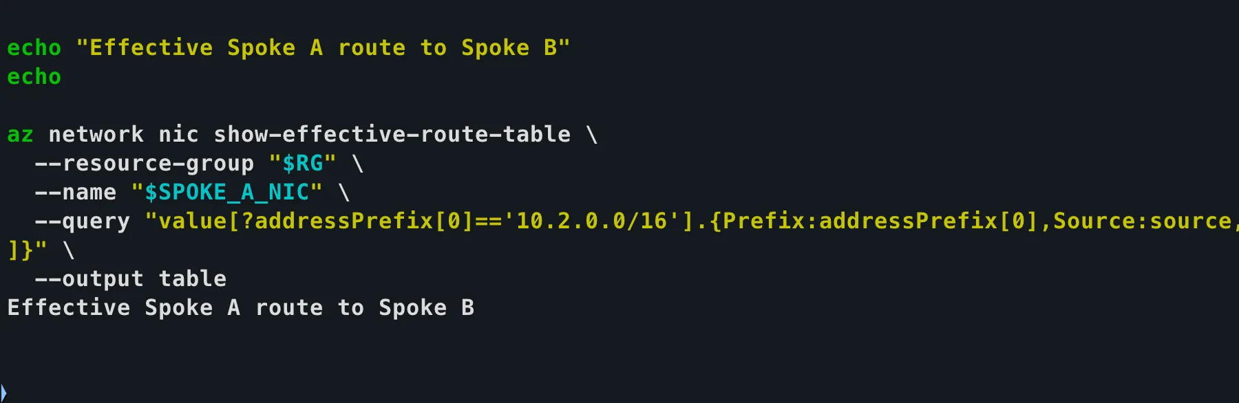
This capture shows the focused effective-route query. Its empty result area is not evidence of a working route; a valid post-configuration check must return a row for 10.2.0.0/16.
For a Spoke A workload, confirm that the effective route for 10.2.0.0/16 resolves to:
Next hop type: VirtualAppliance
Next hop IP:   10.0.0.4
Repeat the check in Spoke B for 10.1.0.0/16.
The Microsoft peering troubleshooting guide recommends checking effective routes when traffic does not behave as expected. Also verify Network Watcher connection troubleshoot results, NSG flow decisions, and firewall logs for the specific source, destination, port, and protocol.
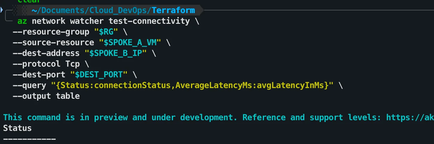
Network Watcher can test the application path and port after routing is configured. This capture contains only the command and table header, so it must not be interpreted as a successful connectivity result.
When Direct Peering Is the Better Design
Routing every spoke-to-spoke flow through a central firewall adds inspection, policy, cost, and another hop.
If two tightly coupled spokes need high-throughput, low-latency communication and central inspection is not required for that path, direct spoke peering can be simpler:
Spoke A ================= Spoke B
          direct peering
The trade-off is deliberate: the direct path bypasses the hub firewall. Microsoft's hub-and-spoke guidance recommends direct peering or Azure Virtual Network Manager connected groups for selected spoke pairs when that trade-off is acceptable.
I do not build a full mesh by habit. As the number of spokes grows, the number of peerings and the operational burden grow with it.
The Virtual WAN Exception
The statement "the hub does not route" applies to an ordinary customer-managed hub VNet.
A Standard Azure Virtual WAN virtual hub is different. Microsoft documents that the virtual hub contains a router and supports transit connectivity between connected VNets. That is a managed transit architecture, not transitive VNet peering.
This distinction matters because the diagrams can look similar:
- Customer-managed hub VNet + peerings: no automatic spoke-to-spoke transit.
- Standard Virtual WAN virtual hub + VNet connections: managed transit routing is supported.
Name the architecture precisely before troubleshooting it.
Troubleshooting Checklist
- Confirm both hub-to-spoke peering relationships show Connected in both directions.
- Confirm all appliance-routed peerings allow forwarded traffic.
- Confirm Spoke A has an effective route for Spoke B through the firewall or NVA private IP.
- Confirm Spoke B has the symmetric return route for Spoke A.
- Confirm the route tables are associated with the correct workload subnets.
- Confirm Azure Firewall or NVA policy permits the required flow.
- For a VM-based NVA, enable forwarding on the Azure NIC and inside the OS or appliance.
- Confirm NSGs, the guest firewall, DNS, and the destination service allow the test.
The Takeaway
Two spokes peered to the same hub are not automatically connected to each other.
The hub-and-spoke drawing shows topology. It does not create transit.
For spoke-to-spoke communication, choose one explicit design:
- Route both directions through Azure Firewall or an NVA with symmetric UDRs and forwarded traffic enabled.
- I create direct spoke peering when bypassing central inspection is acceptable.
- I use a managed transit service such as Standard Azure Virtual WAN when that architecture fits the environment.
Then I I prove the path with effective routes and an application-level connectivity test. A green Connected badge on each peering is only the beginning of that verification, not the end.
Official Microsoft References
- Azure Virtual Network FAQ: transitive peering is not supported
- Hub-and-spoke network topology
- Route network traffic with a route table
- Azure virtual network traffic routing
- Connect virtual networks with VNet peering
- Azure Virtual WAN overview
References
- Microsoft Learn - Azure Virtual Network FAQ
- Microsoft Learn - Hub-and-spoke network topology
- Microsoft Learn - Route network traffic with a route table
- Microsoft Learn - Azure virtual network traffic routing
- Microsoft Learn - Connect virtual networks with peering
- Microsoft Learn - Azure Virtual WAN overview